Four recessed LEDs
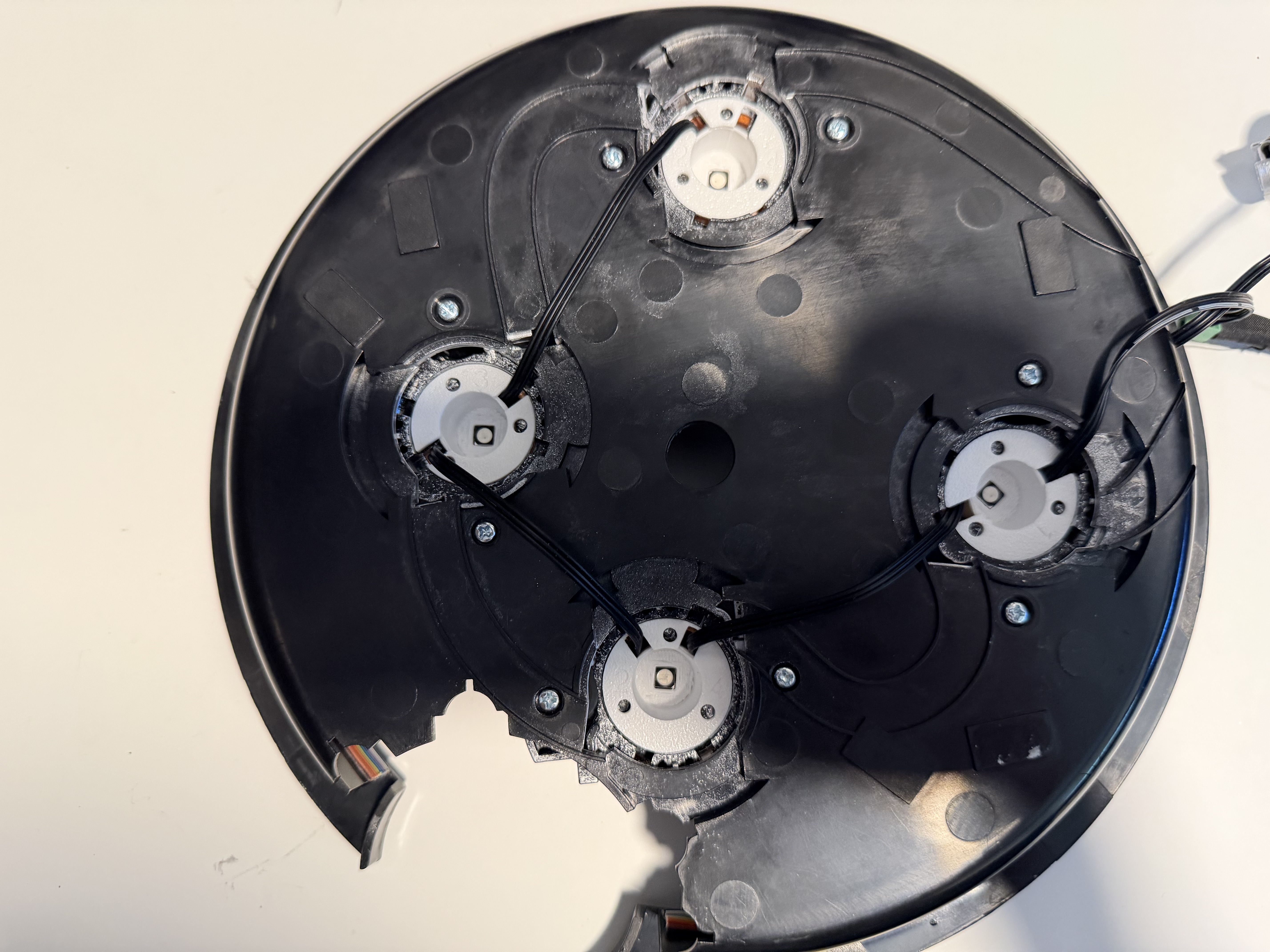
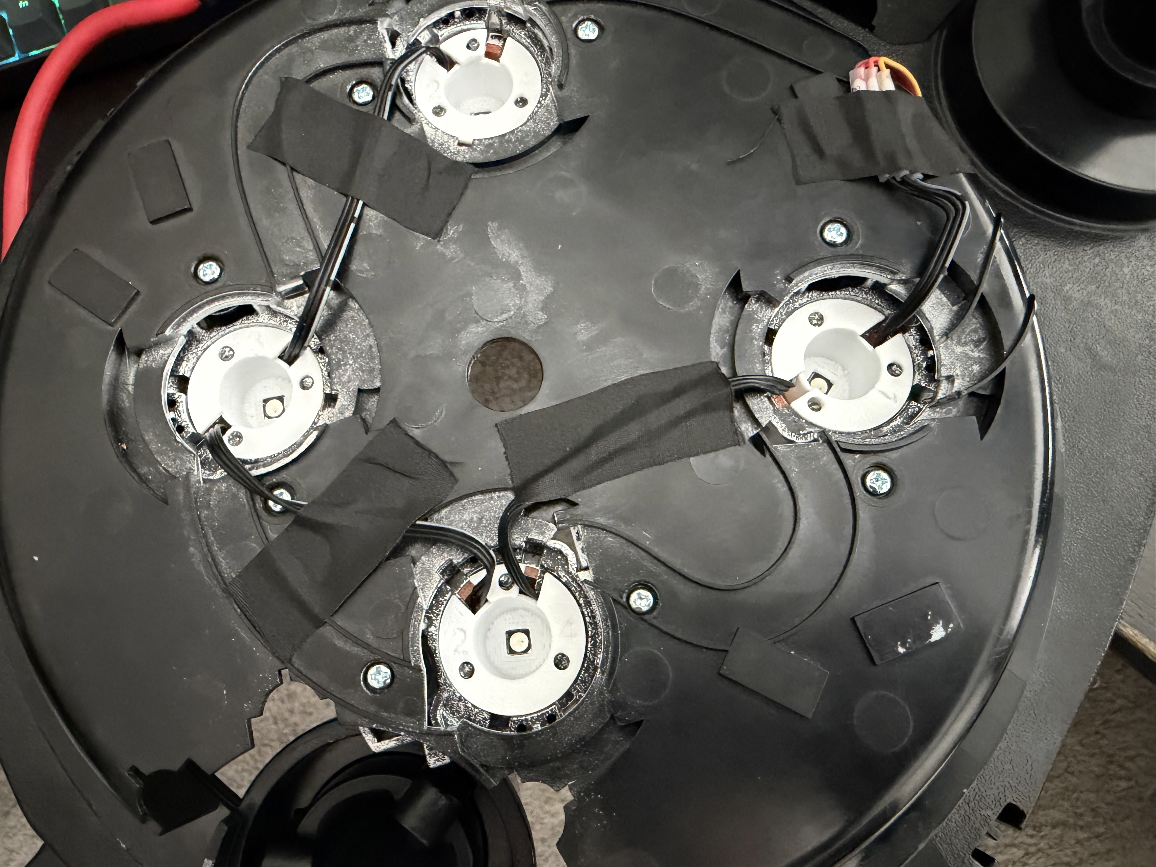
Install one reflector cup in each cyclotron opening.
A2ThreeD installation guide
Hasbro 1984 Proton Pack LED Replacement Kit
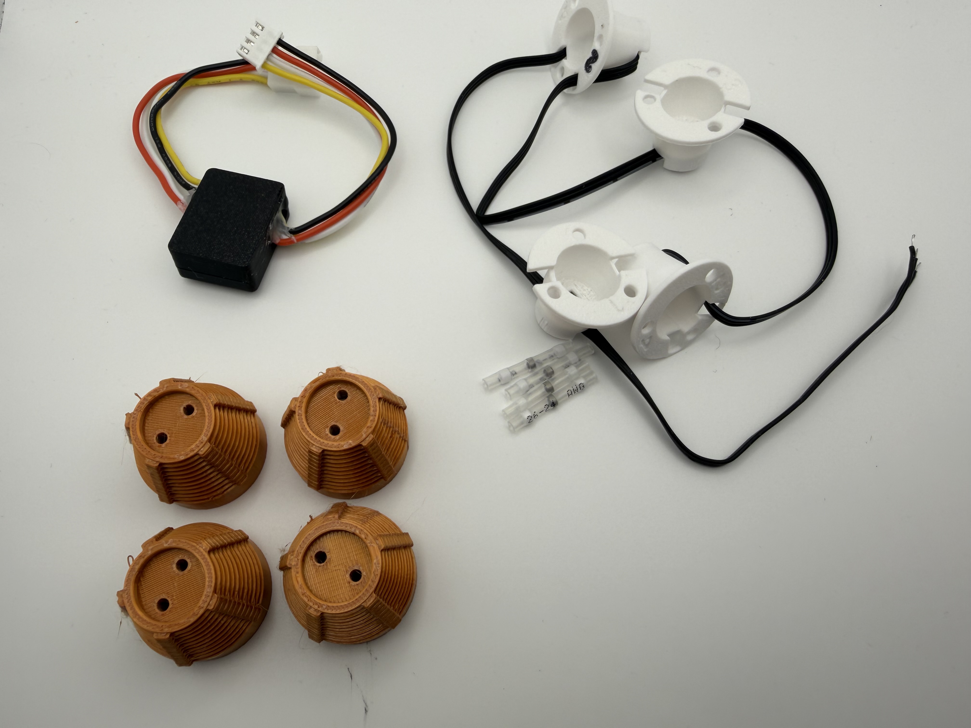
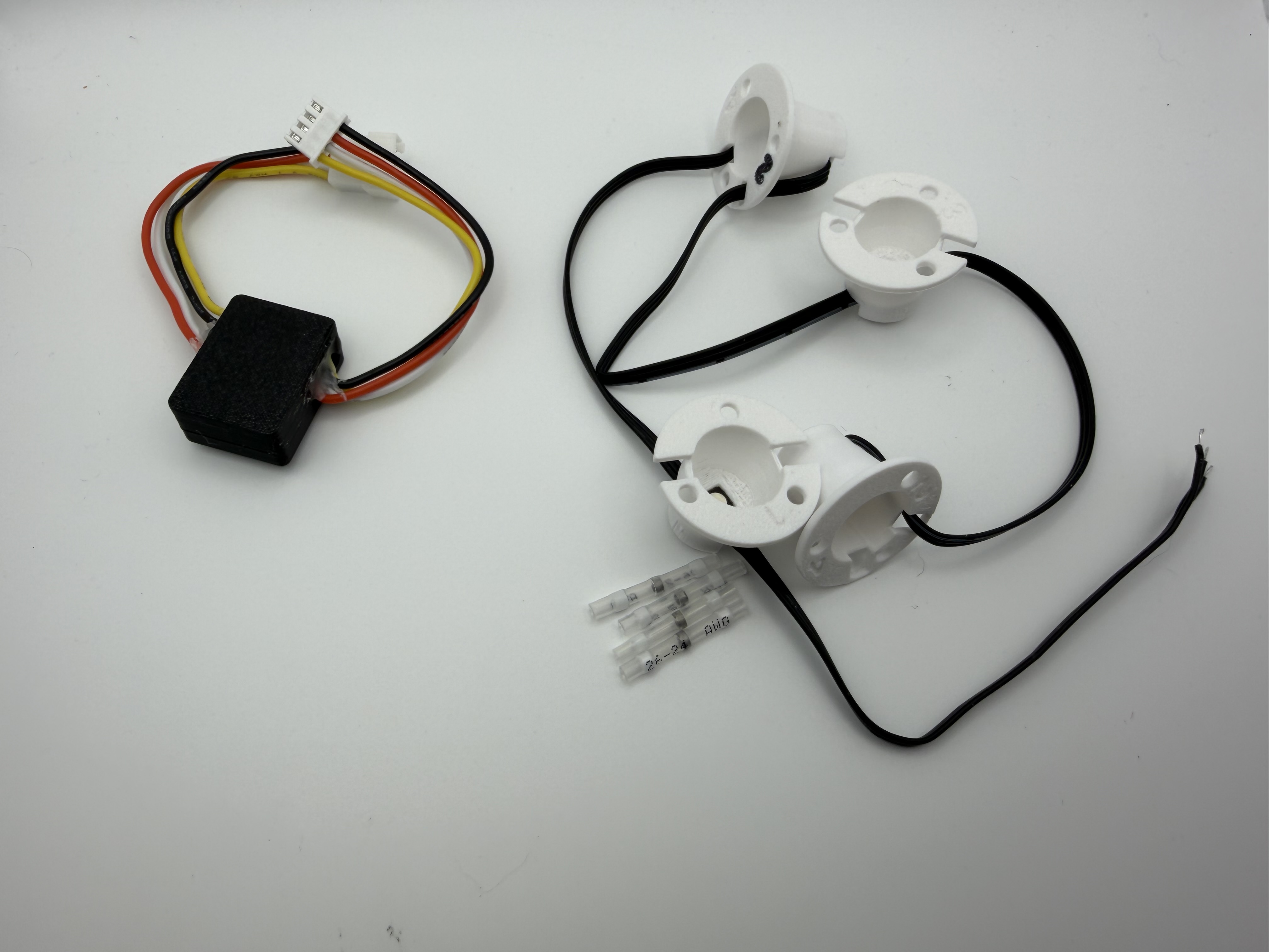
Replace the factory cyclotron LEDs with four recessed RGB LED modules in reflector cups for a deeper, more focused cyclotron effect.
Install one reflector cup in each cyclotron opening.
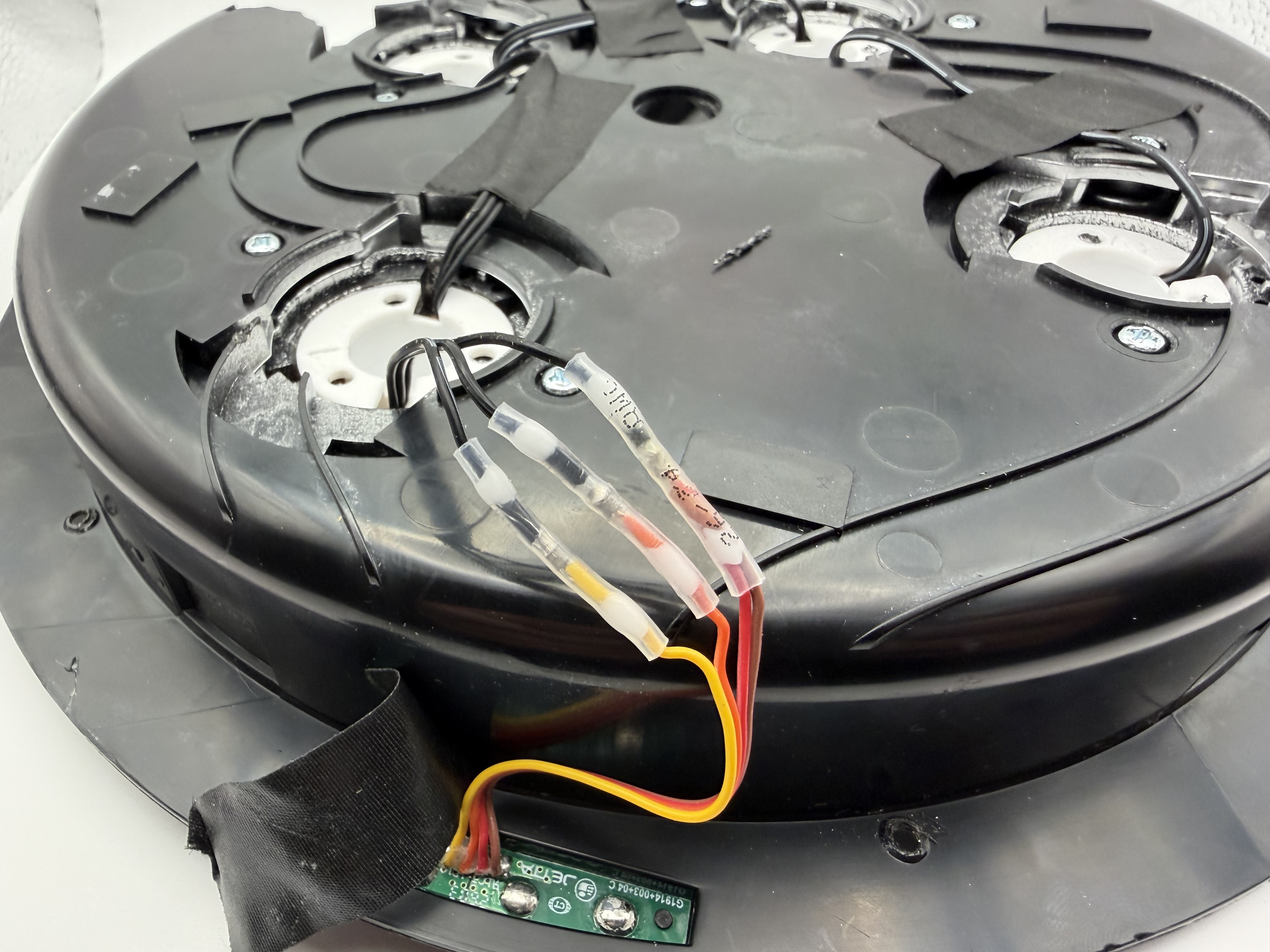
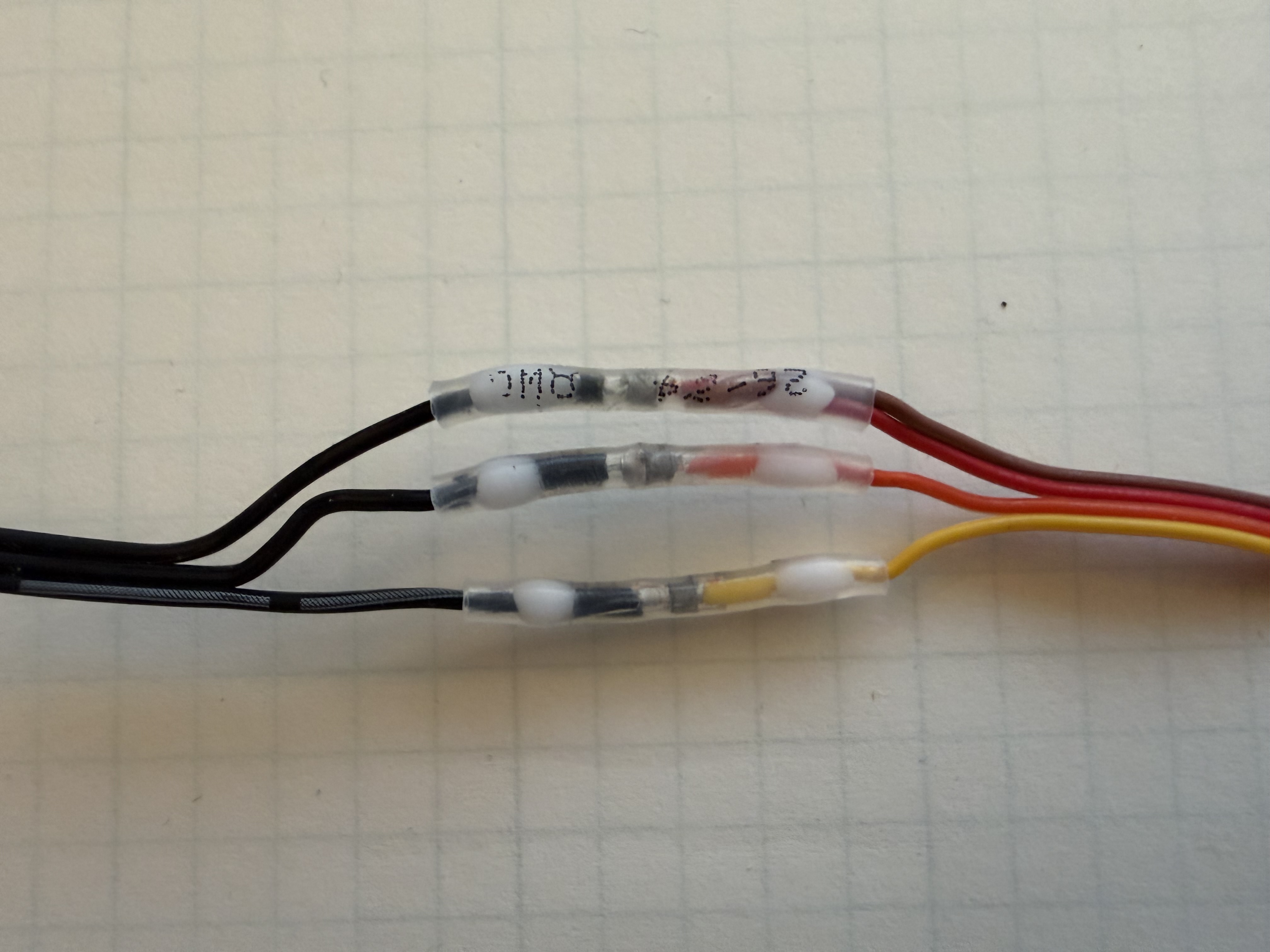
Use the supplied solder-seal connectors or solder directly.
Connect the completed lid to the PixelBro controller inline.
Before you begin
Disconnect pack power before opening the lid or changing any wiring. Work carefully around the original plastic pegs, circuit boards, and ribbon cable.
Video walkthrough
This video demonstrates the recessed LED installation. A separate PixelBro connection video will be added in a future update.
Installation
Follow the steps in order. The current guide includes photos for the kit, reflector placement, and wiring stages; more step photos can be added as they become available.
Unscrew the shock mount/bellows and slide off the bumper. Then remove the cyclotron lid from the pack.
Carefully use automotive panel tools or similar prying tools to pop the two lid halves apart. During seperation, you may break some of the pegs that hold the halves together. However, the lid will still be able to go back together later. There are also other community noted modifications you can do to make re-assembly via screws or glue should this concern you.
Cut the wires for the original cyclotron LEDs about 2–3 inches away from the small circuit board with the pegs on the opposite side.
Using flush cutters, cut only the tops of the mushroom-shaped pegs on each original cyclotron LED circuit board. Lift or pry all four modules out with their wiring intact.
Do not remove the rest of the black plastic pegs. They are used to locate and secure the replacement reflector cups.
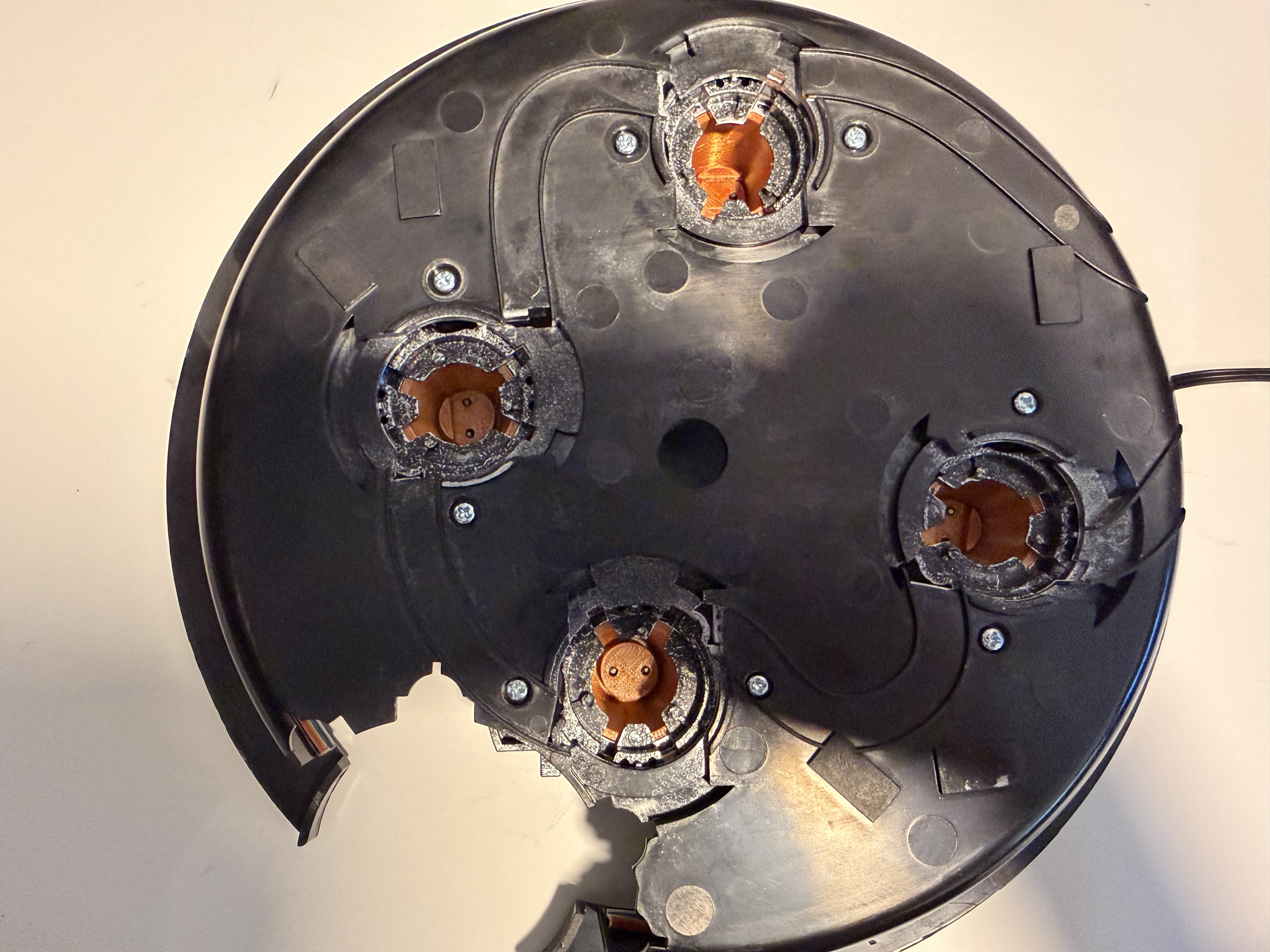
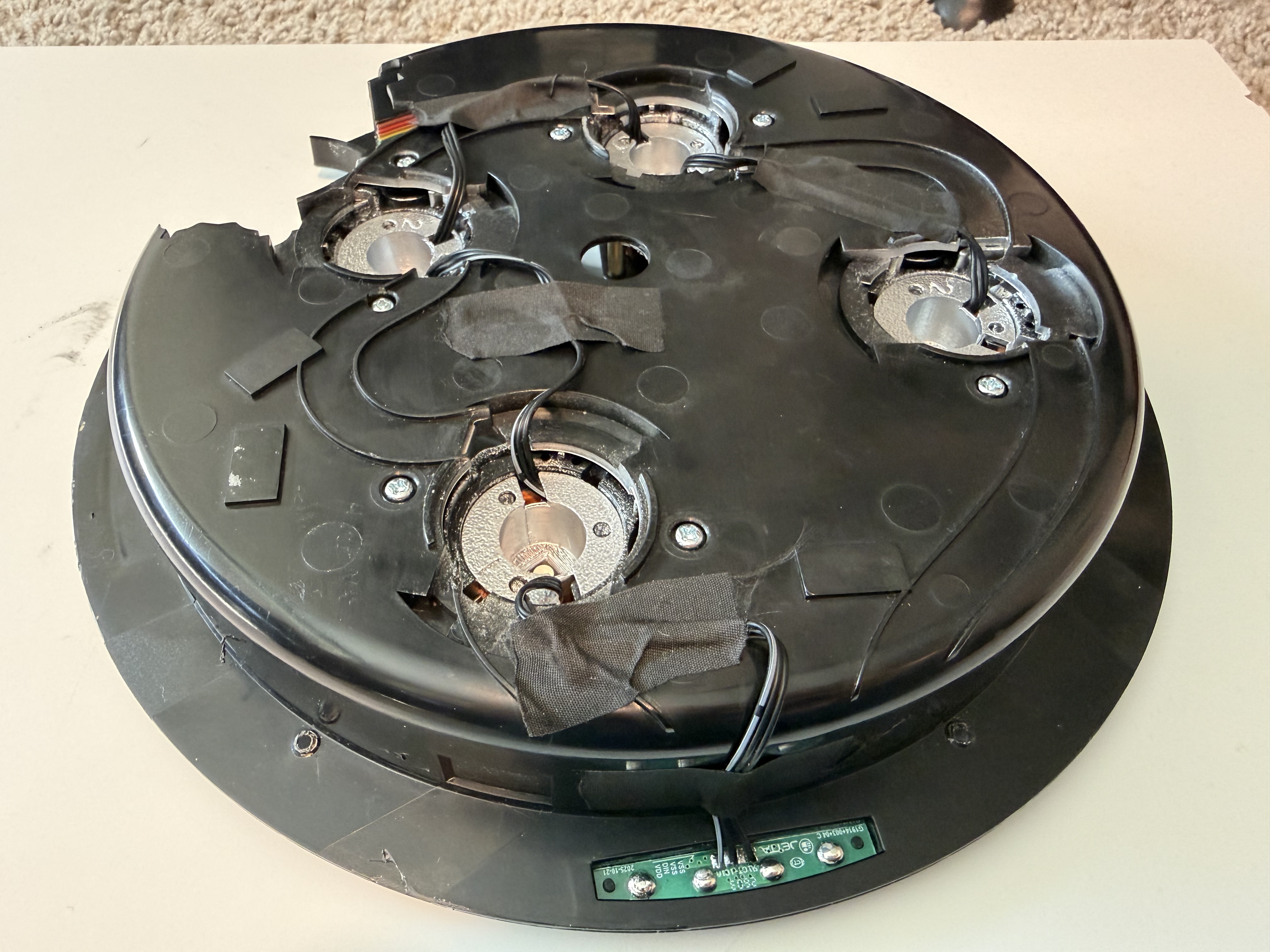
Install each reflector cup in its correct position. Looking down at the inside of the lid with the PCB, peg, and original wire on the right:
Carefully twist each cup into position so its holes line up with the remaining pegs, then press it into place. Watch the wiring and route it through the slots. Secure the wires with tape. Hot glue may also be used to hold the reflector cups in place.
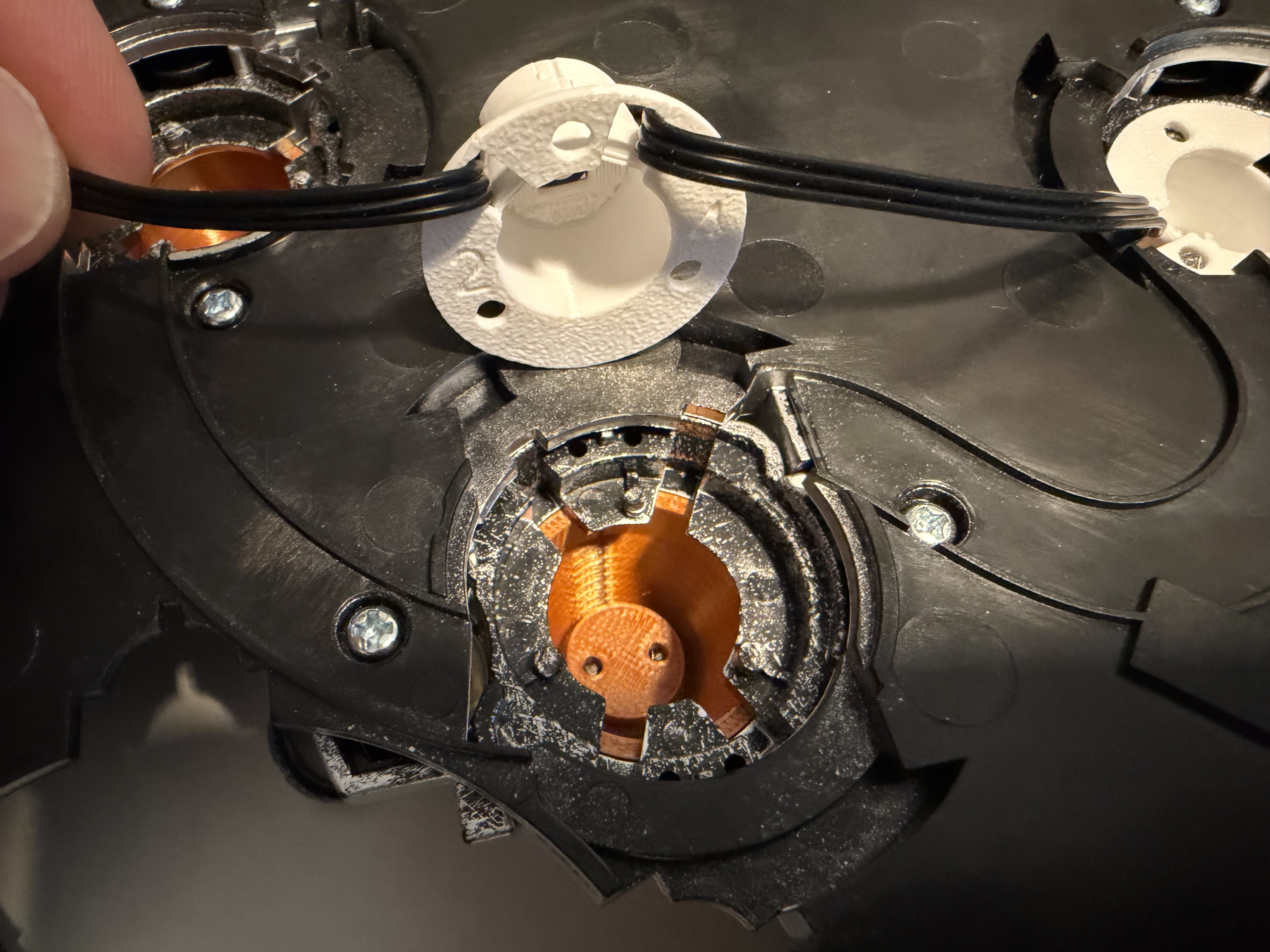
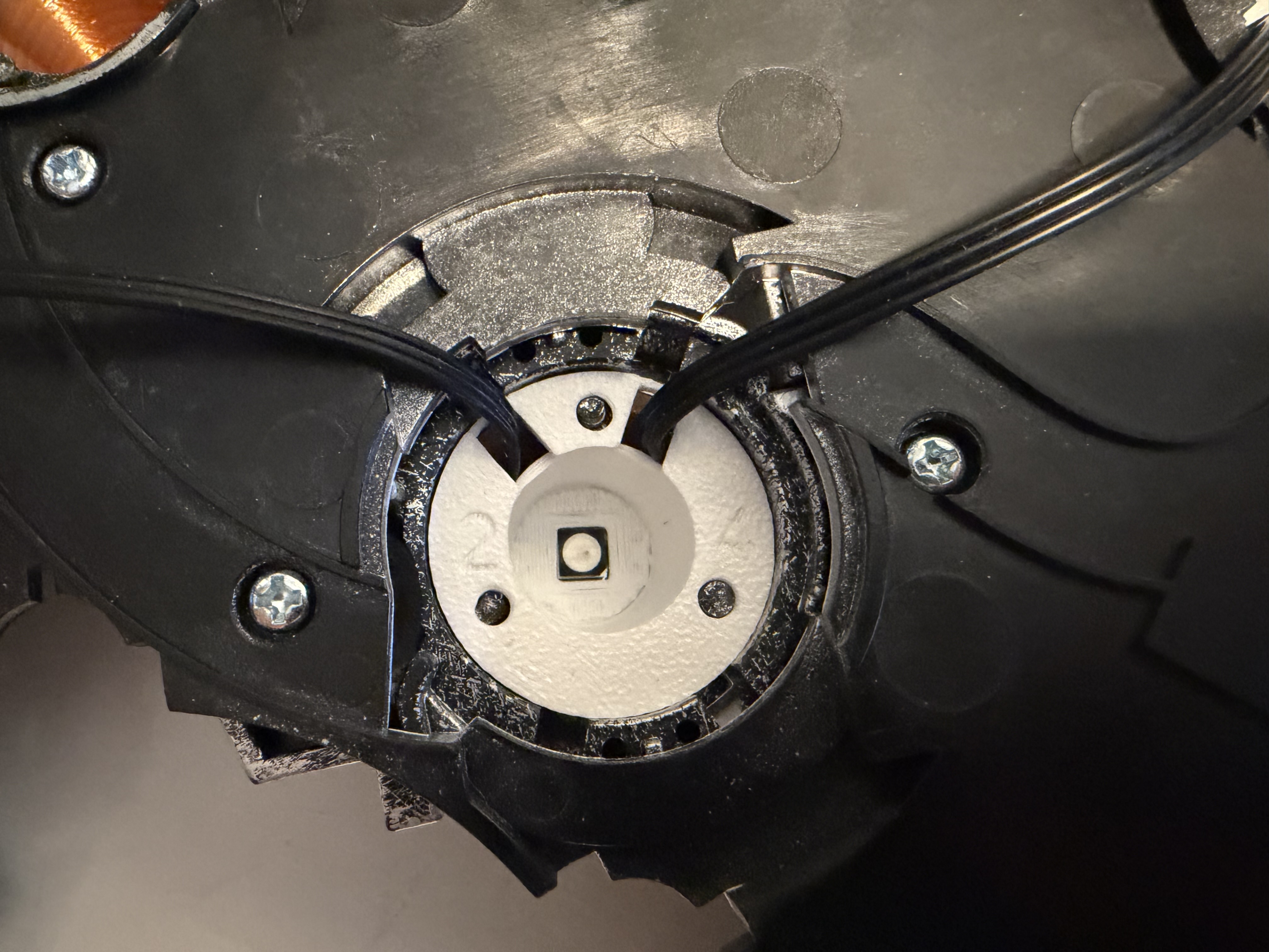
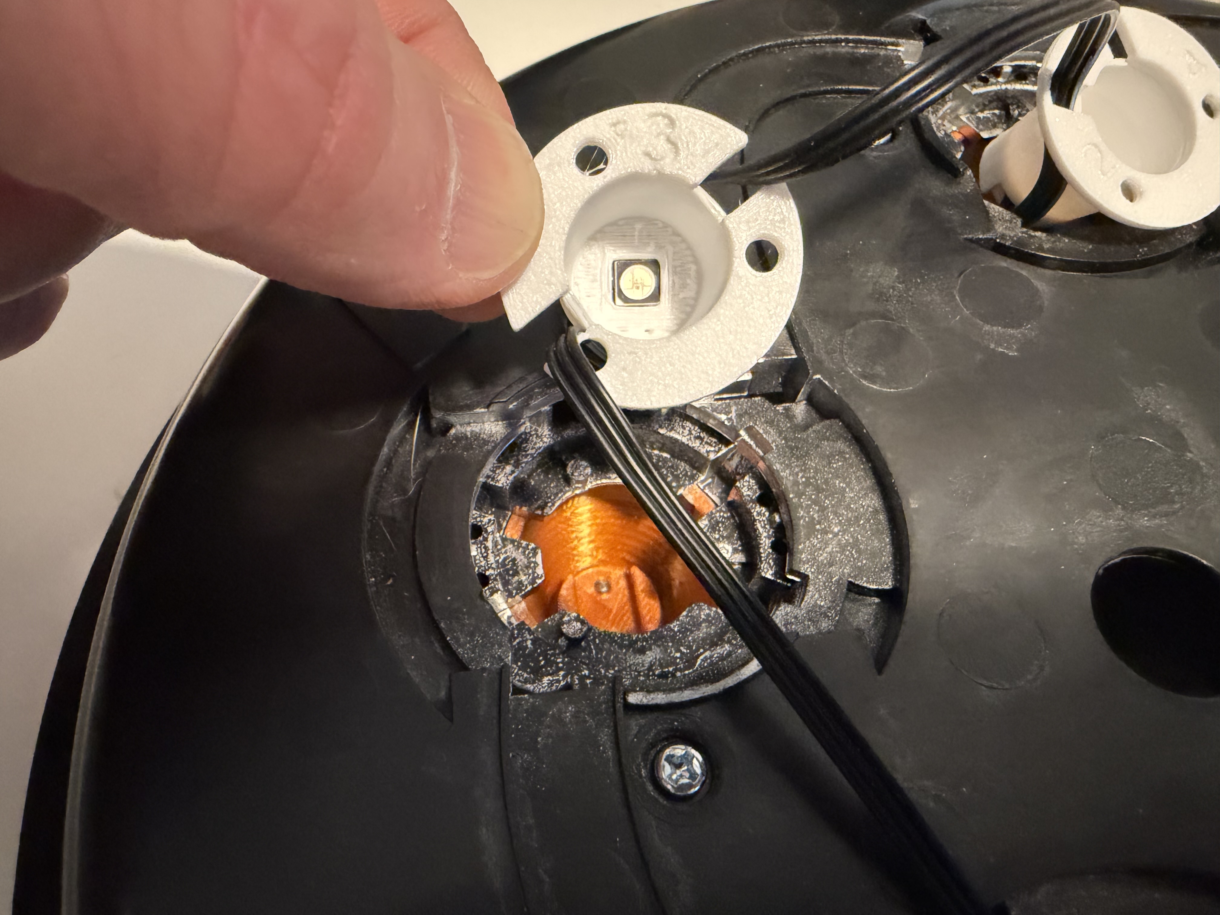
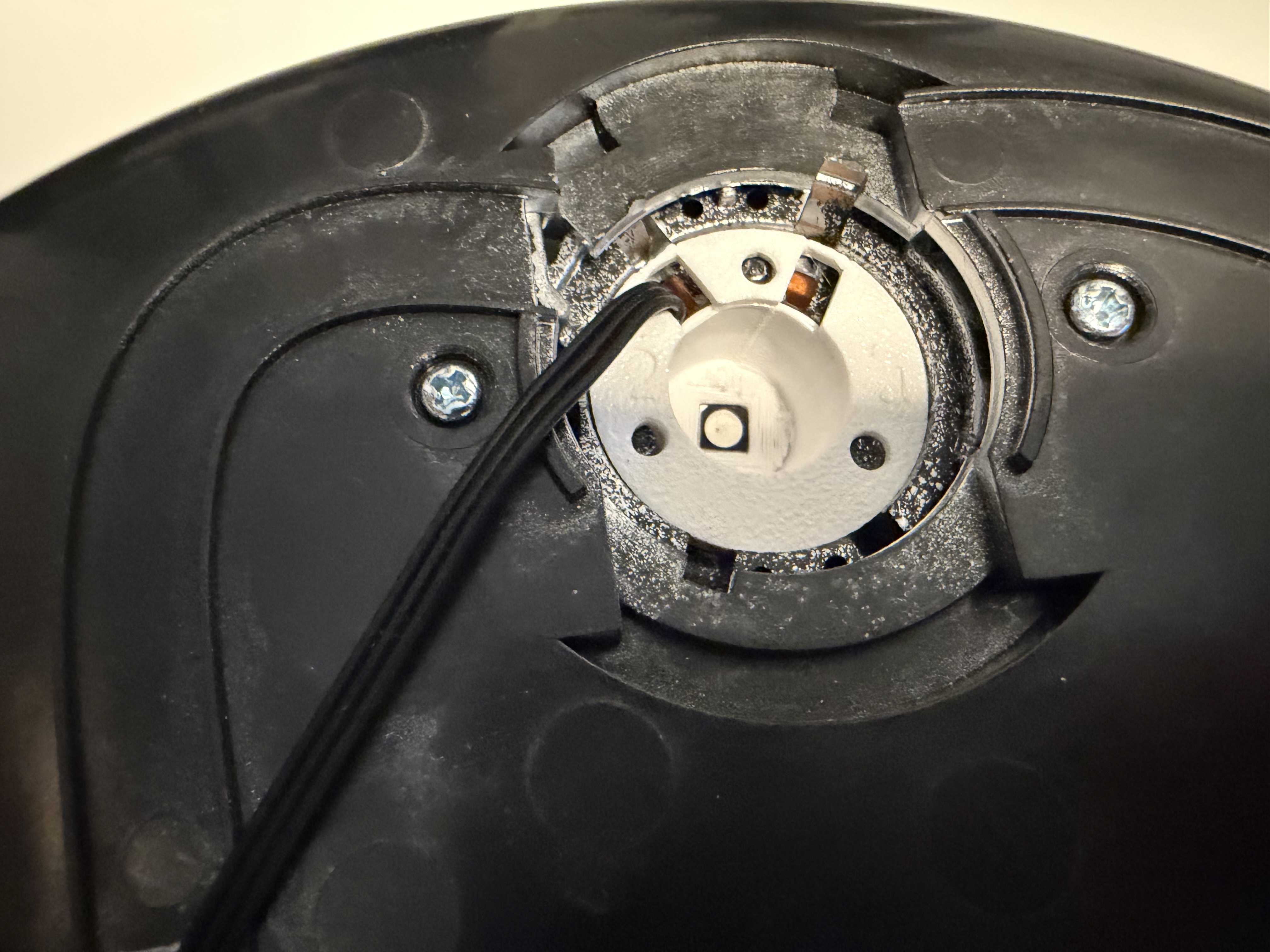
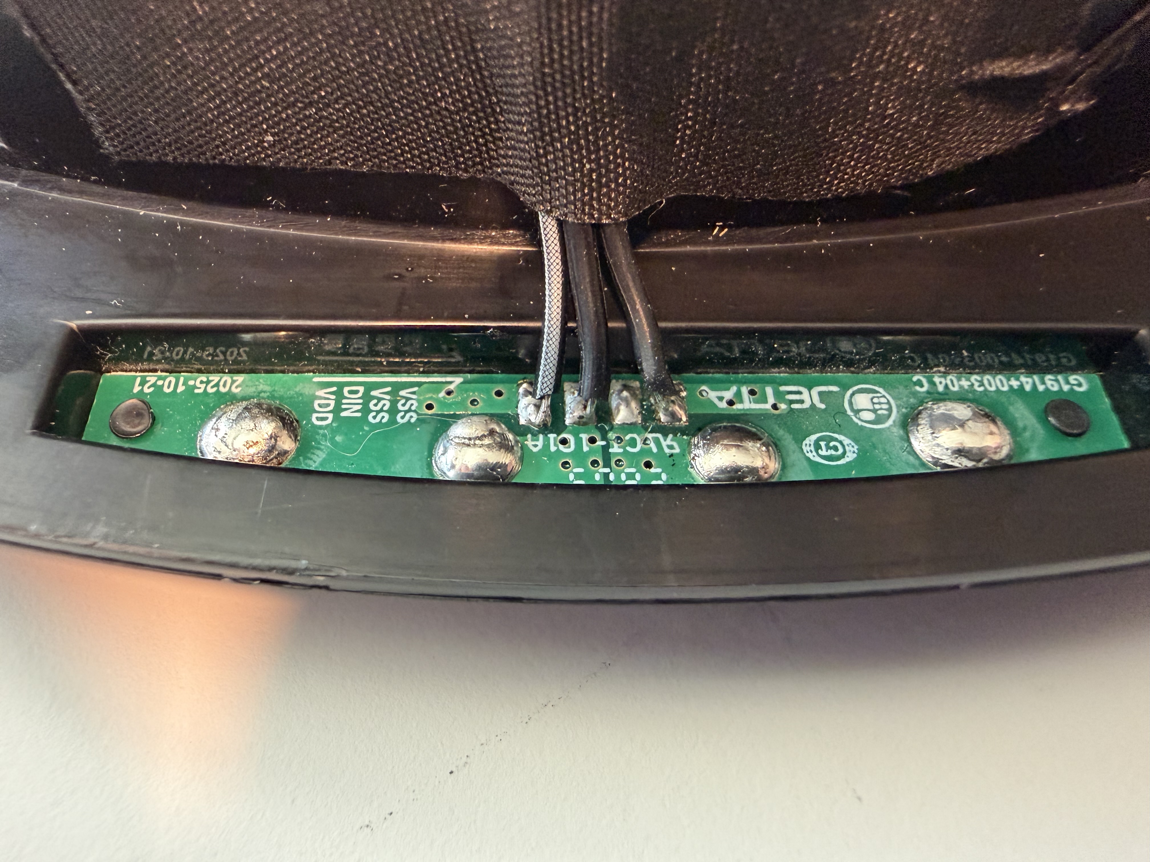
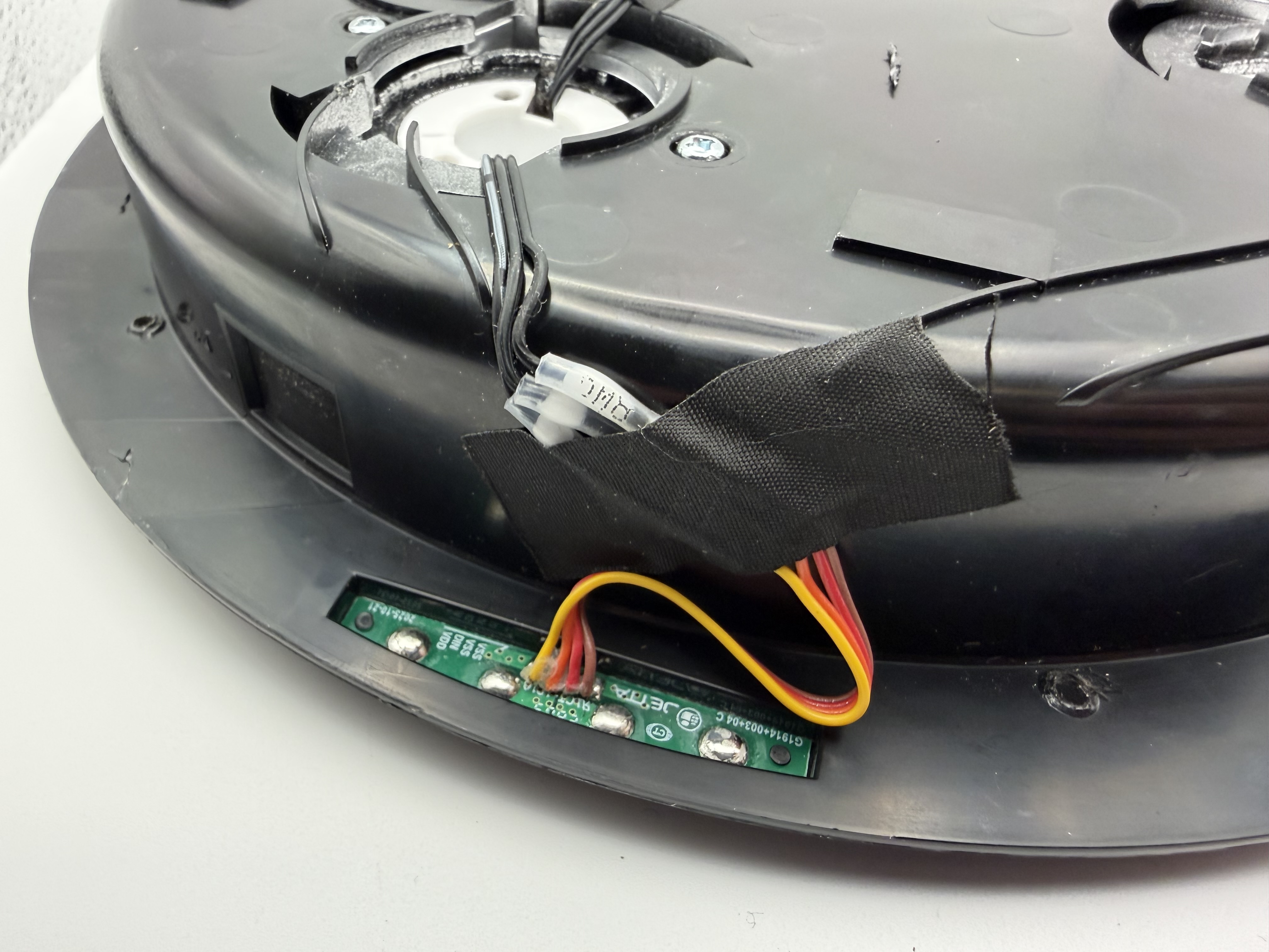
Carefully separate the four original wires on the ribbon cable. Strip about 1/4 inch from each end to expose the copper conductors.
Option A · Supplied solder-seal connectors
Insert the wires into opposite ends of the connectors until the copper meets in the middle. Use a heat gun to shrink each tube and melt the solder in the center, fusing the wires together.
Insert the red and brown wires together into one end of the connector for the final connection.
Option B · Direct soldering
Instead of cutting the ribbon cable, you may desolder the original ribbon cable from the pogo-pin PCB. If you are looking straight down at the PCB where the four original wires were connected:
Important: Bridge the final two pads together. Otherwise, lid detection will not work.
Remove the back cover of your Hasbro 1984 Proton Pack so you can access the factory electronics PCB.
Disconnect the cyclotron ribbon cable from the factory PCB in the upper right. The cyclotron LED connector is a four-pin ribbon cable with a ferrite bead and yellow, orange, red, and brown wires.
Plug the PixelBro controller’s female connector into the factory cyclotron port on the factory PCB.
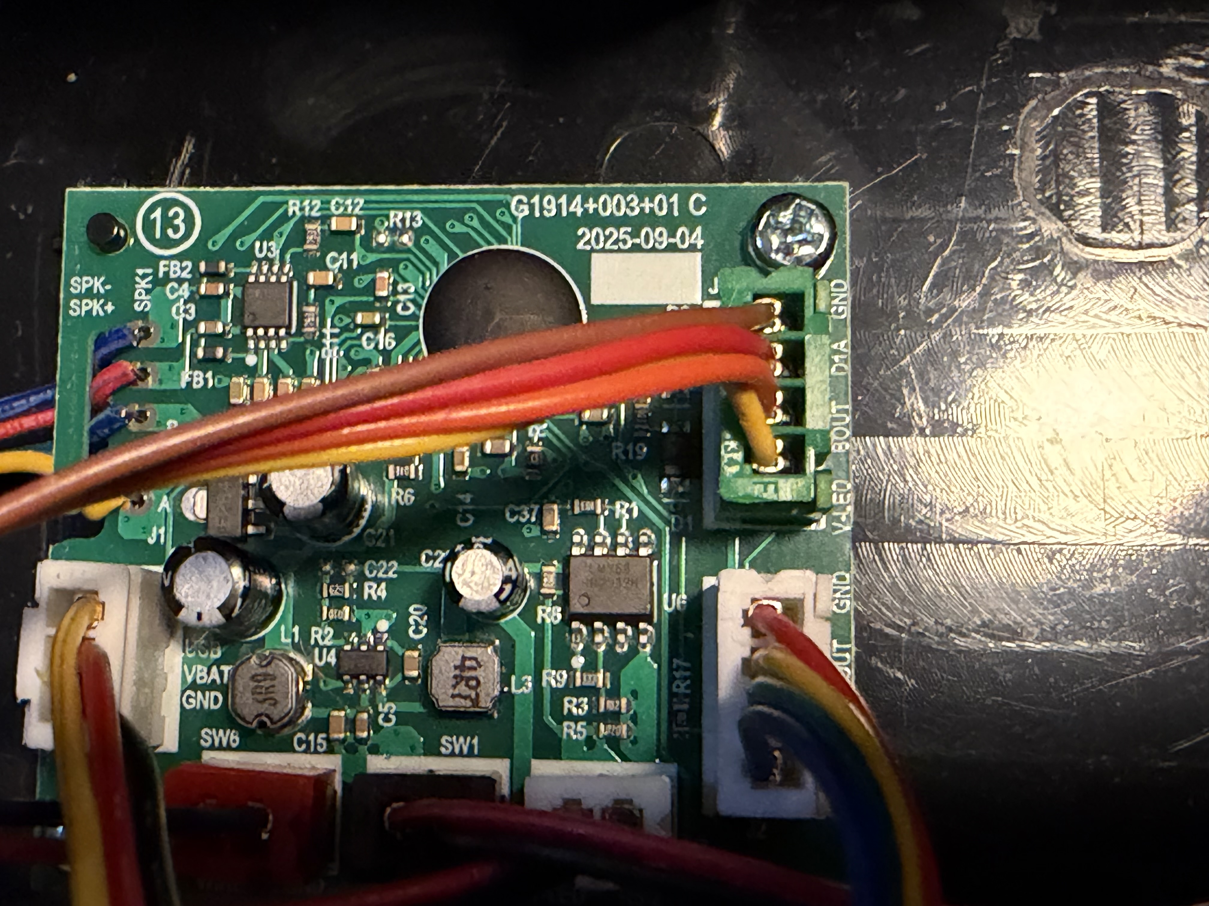
Plug the factory cyclotron wiring into PixelBro’s female four-pin connector and secure the wiring so it cannot be pinched when the pack is reassembled.
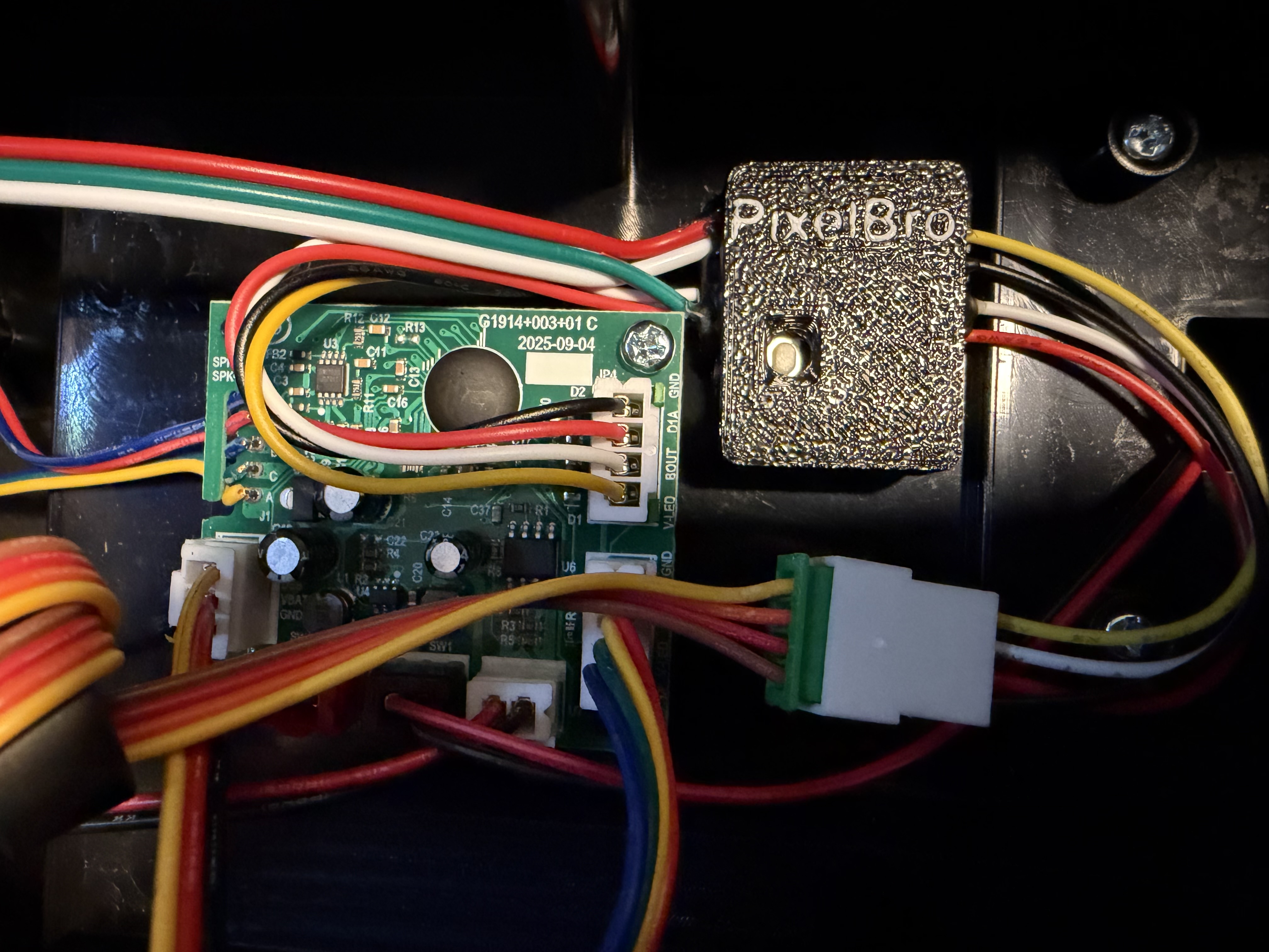
Put the cyclotron lid back on the pack before reassembling everything. Power on the pack and verify that the recessed LEDs and lid detection work properly.
Plug PixelBro into your computer using USB-C, then open pixelbroconfig.a2threed.com to upgrade the firmware or perform advanced configuration.
If you purchased the kit that includes the emitter cone upgrades, you can install them at any time on the back of the cyclotron lid. Remove the four screws from each emitter top, then pop out the original cone and install the replacement.